Flixborough —
Some Additional Lessons
Presentation by J. I. Cox (FELLOW)
(Reprinted from The
Chemical Engineer, May 1976, Issue No. 309, pp.353-8)
NOTE
This paper began life as a presentation to an IChemE symposium in
December 1975. It and other papers presented at the symposium
then appeared in The Chemical Engineer in April/May 1976 and
later was specially reprinted by virtue of its insight into the
causation hypotheses. This website version - and its companion
piece Flixborough Revisited –
appears with passages highlighted in red if
thought to be of contemporary interest and/or directly relevant
to the more contentious issues at the Public Inquiry.
Introduction
The explosion at the Nypro
(UK) Ltd caprolactam plant at 4.53 p.m. on 1 June 1974
took place in a large cloud of cyclohexane that escaped when a
temporary pipe collapsed. The Court of Inquiry into the
Flixborough Disaster decided that the defects of this plant
modification, coupled with a rise in operating temperatures and
pressures, was responsible. They state (Para 209) “the
disaster was caused by the introduction into a well-designed and
constructed plant of a modification  which destroyed its integrity”.
In consequence of this
technical assessment, subsequent discussion of the report has
concentrated on management issues. Little of general application
has emerged so far from the technical investigations, and Nypro
may be the only company to appreciate the full significance of
the investigations conducted during the Public Inquiry —
although industry is of course well aware of the general
implications.
In this presentation,
lessons for plant safety are considered without regard to whether
these had, or were thought to have had, direct bearing on the
disaster. In adopting this approach, alternative explanations for
the disaster (Fig 1) are recalled to clarify the technical issues
and to emphasise the degree of probability of such phenomena
occurring (again). The paper thus serves to indicate alternative
views on the cause of the disaster - though the main purpose of
the Nottingham IChemE Symposium was to draw attention to the
technical lessons.
The investigations are
considered in greater depth by Cottrell and Swann1 and
Ball2 (metallurgy) and Gugan3 (combustion),
whereas this paper deals with the overall implications.
1 Water Sprays
A 20 inch pipe and bellows
assembly was installed as a temporary bridge between the fourth
and sixth cyclohexane oxidation reactors (Fig 2) when the fifth
reactor was removed at the end of March 1974 following the
discovery of a ½ long crack in the stainless steel lining. The
inner crack had developed from a 6 ft crack in the mild steel
cladding and this, in turn, had been caused by nitrate corrosion
from a temporary spray of cooling water (to which nitric acid had
been added for pH control).
This spray was intended as
protection against a most unlikely event. Several months earlier
a small air leak had been noticed in the air supply line to the
fifth reactor. Nypro’s criteria for defining a leak were
more stringent than often used in the industry. It was decided
that protection was needed in case the air compressor stopped
unexpectedly and the block valves and compressor failed to
prevent back-flow. The spray had been intended to condense any
cyclohexane that might escape.
It is ironic that this
ultra-cautious action by a “safety conscious” company
(Paras 201, 202) was the starting point for the disaster. Users
of water sprays, whether to dilute leaks, improve heat exchanger
performance, or any other of the numerous reasons for their
application, are warned (Para 212) that contaminated water can
cause stress corrosion. Another lesson is that safety measures
often involve an element of compromise between alternative
hazards and that the blind application of ‘rules’ can
have unexpected results.
2 Court Investigations
These dealt with the mode
of failure of the 20 inch pipe assembly. The Court concluded that
the assembly was subjected to conditions of pressure and
temperature more severe than any which had previously prevailed”
and which were sufficient to and did cause the assembly to
rupture, and thus to release large quantities of cyclohexane.
Such cyclohexane formed a cloud of vapour (mixed with air) which
exploded” (Para 225).
Experiments with a
duplicate assembly were conducted on behalf of the Court by the
Safety in Mines Research Establishment (SMRE)4. They
were unable to reproduce the jack-knife of the
disaster (illustrated in Fig 3c), but did achieve double-bellows
instability (‘squirm’ in the Court’s terminology)
just above normal working conditions (Fig 3a). It was established
(Para 123) “that rupture initiated by jack-knifing was
unlikely to occur before relief valve pressure” and
that, if a squirm did occur without bellows rupture, “the
assembly with both bellows squirmed would not then rupture save
at pressures above relief valve pressure”.
By elegant mechanical
engineering reasoning, Professor Newland reconciled the SMRE
experiments with a jack-knife collapse5. He calculated
that the initial downwards movement towards the ‘squirm’
position, under only slightly different conditions to those of
the SMRE simulation tests, could provide kinetic energy to deform
the lower mitred bend and initiate a jack-knife. The results of
his calculations6 are summarised in Table 1 and his
proposed mode of failure is illustrated by Fig 3b (above).
Table 1 shows that, for a
43 inch scaffolding span (as used by SMRE), squirm would occur at
9.7 kg-cm-2 for the expected bellows
stiffness of 2 800 lbf/in. As this is only 0.2 kg-cm-2
into the 9.5-10.8 kg-cm-2 range for jack-knifing, the
chances of a subsequent jack-knife may be expressed roughly as 0.2/1.3
(about 15%) - an improbability confirmed by the SMRE squirm
without jack-knife at 9.8 kg-cm-2.
By contrast, the 78 inch
span favoured by the Court (Para 124) would allow squirm below 9
kg-cm2 with no chance of subsequent jack-knifing. So
it had to be assumed (Para 125) that the Flixborough bellows were
stiffer than 2800 lbf/in. The fact that they failed to squirm at
9.2 kg-cm-2 earlier the same day does not validate
this assumption as the temperature was then lower than 150°C (Para
86) - probably 120°C. This reinforces the admitted “low
probability” (Para 191) that a jack-knife would be
caused by severe operating conditions.
TABLE 1
Internal pressures
causing squirm and jack-knifing after squirm
Internal Pressures (kg-cm-2)
|
Span
of scaffold supports
|
Temperature
(a)
|
For
Squirm (Fig 3a)
Bellows axial stiffness
(lbf/in)
|
For
Jack-Knifing after Squirm (Fig 3b) Probabilities
|
| |
|
2800(b)
|
3300
|
0%
|
50%
|
100%
|
|
43"
|
150°C
|
9.7
|
11.3
|
9.5
|
10.1
|
10.8
|
| |
160°C
|
9.5
|
11.1
|
9.3
|
9.9
|
10.6
|
|
78"
|
150°C
|
8.8
|
10.3
|
9.3
|
9.9
|
10.6
|
| |
160°C
|
8.6
|
10.1
|
9.1
|
9.7
|
10.4
|
N.B. (a) Operating conditions, 155°C and 8.6-8.8 kg-cm-2.
(b) A compromise between 2860, calculated by the manufacturers,
and 2752,
the actual value of the SMRE test bellows, made from the same
material batch.
This improbability in no
way invalidates the conclusion (Para 63, 209) that the 20 inch
pipe assembly as installed was quite unsuitable and the
recommendations with respect to non-compliance with BS3351:1971
stand. The bellows and pipe were shown to be separately suitable
for the duty but the assembly was not pressure-tested in situ.
Had this been done pneumatically at 155°C, the probable
result would have been a squirm as in the SMRE test (Fig 3a) and
the defective design would have been revealed.
In view of the dangers
associated with pneumatic testing, BS3351 recommends hydraulic
tests and the Court hypothesises (Para 73) that “Such a
test would almost certainly have caused failure”. Whether
or not this is right, it would have been relevant to comment that
hydraulic testing would have been impracticable on the plant as
designed and it is advisable to design provision for pressure-testing
of sections of plant.
With respect to the content
of BS335I 1971 it could have been mentioned that reference to
“Advice of the manufacturers” is not satisfactory in a
British Standard. In this case the bellows’ manufacturers
supplied their clients (the plant constructors) with their ‘Designer’s
Guide’ but Nypro did not receive copies until two months
after the disaster. It is unrealistic to assume, as do British
Standards, that users of plant equipment have ready access to
manufacturer’s advice at all relevant times.
3 Plant Conditions
Operation
The disaster occurred
whilst cyclohexane was recycling at essentially working pressures
and temperatures awaiting a delivery of nitrogen to supplement
the stocks needed for shutdowns and emergencies. Overpressure
was a potential hazard during this prolonged start-up period as
the pressure control valve (PCV on Fig 2) was not suitable for
these conditions and was isolated by block valves. This could
have been avoided by the provision of a tight shutoff control
valve or a split-range controller.
However, the pressure was
not uncontrolled: the inlet block valves were also closed (to
prevent ingress of vapour) and the temperatures were on automatic
control before the shift hand-over. In this situation a rise in
pressures and temperatures required either deliberate operator
intervention or equipment malfunction. Neither hypothesis was
substantiated by the settings of the valves examined after the
explosion and the presumption (Paras 87, 225) that the
deceased allowed pressures and temperatures to reach levels “more
severe” than “had
previously prevailed” is not readily
accepted by those who know the plant and the way it was
operated. Nevertheless even the possibility that this could have
occurred emphasises the need for attention to safe design for
start-up as well as normal operation.
Nitrogen
During normal operation an
automatic shut-down and purge of the oxidation reactors took
place if the ‘Low Low Nitrogen Level’ was reached (so
that oxidation stopped when nitrogen stocks were too low to cope
with an emergency). If this had happened by mistake during warm-up,
there might have been a pressure rise of about 0.8 kg-cm-2
in five minutes - assuming the purge was not
stopped.
Although this theory was
rejected (Para 88) - there was no supporting and some opposing
evidence - it illustrates an important and not uncommon problem.
A safety device (in this case the automatic nitrogen purge) can
be a hazard in circumstances other than those for which it was
designed. So provision for deactivation was allowed - an option
which accords with the reality and complexity of plant operation.
(In contrast, the Factory Inspectorate advocated rigid immutable
written instructions for plant operators and that deactivation of
such safety devices not be allowed during plant operation).
Internal
explosion
King7 suggested
a mechanism dependent upon plant scale - a significant
temperature difference in the fourth oxidation reactor allowing a
‘cool’ slug of water at the bottom of its otherwise hot
contents. At 4.53 pm on 1 June the water might have boiled
unexpectedly and caused a sharp pressure rise. Although feasible,
the amount of water and the delay before boiling both appear
larger than possible at Flixborough. However, designers should be
alive to the possibility that new phenomena become significant
for large plant sizes. It is of interest also that King’s
hypothesis gains credibility from the temporary absence of the
stirrer from reactor 4. This illustrates how an apparently
innocuous modification may have unexpected significance. But
similar plants have not recorded sudden pressure rises during
start-up, even when operating without agitators and after water
displacements.
Other internal explosion
mechanisms were suggested and rejected. All depend upon detailed
chemical reactions that do not have general application and so
are not discussed herein. The relevance of an internal (or an
external) explosion is that it circumvents the problem that a
slow rise in internal pressure was shown by the Court’s
investigation (section 2) to be unlikely to cause the jack-knife
failure of the disaster.
4 Zinc embrittlement
The 20 inch pipe would
have jack-knifed from a fairly small external shock wave: certainly
no more than 4 psi, possible as little as 0.01 psi. So an
external explosion, especially if from above, could provide an
explanation for the jack-knife and the presence of foreign debris
(Court Plate 10 and Fig 3c), which must have been trapped in
mid-flight.
The centre of the big
explosion was east south east of the oxidation reactors (Fig 4),
and two fan rotors had landed 60 ft and 140 ft away, roughly at
right angles to the direction of the main blast.
The finned tubes of the southernmost fin-fan cooler (from which
these fan rotors had been ejected) had shattered into 2-3 ft
lengths and, since the supporting struts were on the west, the
rotor must have passed through the overhead bank of finned tubes.
As the collapse of the plant structure would have blocked this
flight path, a local explosion seems to have occurred before
the collapse of the bank of fin-fan coolers (which presumably
fell with the big explosion).
(N.B. The furthest flung
Fan Rotor landed on waste ground and was not engulfed in the
subsequent general fire. There were signs that the bearings’
grease had begun to melt whilst the rotor was in its normal
position. In addition the rotor was covered in soot from the
flash fire of the main explosion. These facts were consistent
with a fire and explosion in the fin-fans prior to the main
explosion.)
Mr Orbons, a DSM
metallurgist, showed that the shattered tubes had suffered zinc
embrittlement. The fins were galvanised mild steel but the tubes
(of the southernmost cooler only) were stainless. Detailed
studies of zinc embrittlement confirmed that zinc can crack
stainless steel within “a fraction of a second” of
the temperature reaching 800-900°C (Court Appendix II).
So it seemed possible that
a relatively small fire shattered the finned tubes and released
cyclohexane for an explosion in the fan housing. Nevertheless,
evidence for a pre-event9 and apparent sighting of
a fan rotor in flight10 and the eye-witnesses
(right-hand corner, Fig 4) who reported flames from the position
of the fin-fan coolers before the main blast were all discounted
by (Para 164) ‘No evidence of any kind was given to
suggest that this was a reasonable possibility much less a
probability.”
Zinc embrittlement was not
confined to the fin-fan coolers and the phenomenon assumed some
importance in relation to the damage to an 8 inch line (section 7).
Experiments with the galvanised wire used round pre-formed
lagging confirmed (Court Appendix II) that “Zinc from a
wire can cause embrittlement. The wire needs to be close to the
specimen but contact is not essential.” The Court
concluded nonetheless (Para 162) that they “cannot regard
it (zinc embrittlement from galvanised wire) as a real
possibility”.
These conclusions severely
weaken the important warning and recommendation (Para 213) “that
the attention of industry should be drawn to these matter”. The
experiments showed that the juxtaposition of zinc and stainless
steel is very dangerous11 and it is disappointing that
the Court did not recommend that galvanised mild steel integral
with stressed stainless steel should be prohibited, especially
since they accept that “a relatively small but fierce
fire can, if there is a source of zinc nearby, cause a sudden
catastrophic failure”.
5 The Unconfined Vapour
Explosion
Studies of the wreckage,
discharge calculations and wind tunnel simulations all confirmed
that the location and size of the major explosion were consistent
with discharge 20-25 seconds after the collapse of the 20 inch
line. Although most eyewitnesses reported flames some time before
the explosion, Para 93 suggests that ignition did not occur until
the cloud reached the Hydrogen Plant. During the hearings it was
implied that earlier ignition might have prevented the explosion
whereas a slower escape might have merely delayed it.
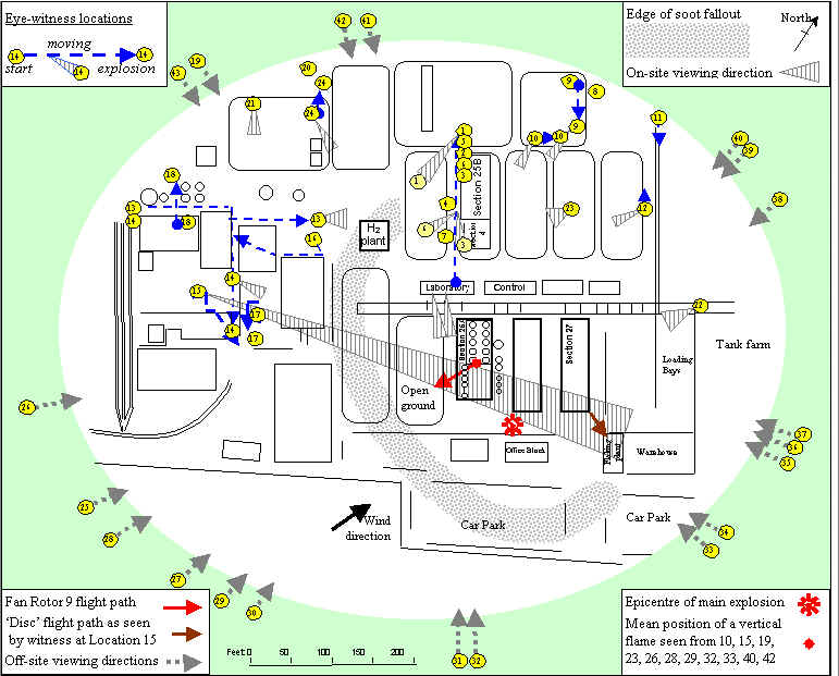
Fig 4 Simplified Site
Plan (omitting details not referenced in paper)
[redrawn for this website in colours and in original
landscape orientation]
Gugan3a
suggests instead that flames were present throughout the escape
but were kept at bay by the rapid expansion of the cyclohexane
cloud. When the discharge slowed, flames moved inwards from
several directions culminating in a highly ‘efficient’
explosion. This is consistent with the 20-25 second period
expected from the discharge calculations and is substantiated by
eyewitnesses12. It implies that the time of ignition
was not relevant to the size of the explosion but that the rate
and quantity of discharge was all-important. Moreover, it
suggests that the inventory of over 200 tons of superheated
cyclohexane circulating through the plant without any isolation
valves was a serious design weakness: the Court’s theory
does not.
Designers of plant
should bear in mind that a high inventory of a critical process
fluid presents a safety hazardand that measures may be needed
to reduce total inventory or instal devices to limit the critical
inventory at risk. Although there are practical difficulties
associated with isolation valves, these are not insurmountable
and it is most disturbing that the Court (Para 203) absolved the
plant design from criticism on this count.
Ignition preceded the
unconfined vapour explosion at Feyzin by an appreciable period,
confirming that Gugan’s theory is feasible with all its
implications for plant design, firefighting and site planning.
It implies that an explosion - not a big fire - can be expected
from a large and fast enough escape and suggests a design
criterion for the numbers of isolating valves needed to prevent
this type of explosion.
6 Partial Collapse of
the 20 inch Line
The foregoing suggested
that, after a small fire and an explosion in the fin-fan coolers,
the 20 inch line could have jack-knifed and, following this
collapse, a large escape of cyclohexane kept the already-present
flames at the periphery of an expanding cloud. But the five
laboratory witnesses with a clear and immediate view of the first
cyclohexane escape did not report an emission from the fin-fan
coolers (Fig 5): their evidence was more consistent with a low-level
escape much nearer the 20 inch line.
Fig.5 – Laboratory viewpoints
A
Plan view showing initial positions of witnesses and
various other features
This led to the hypothesis that a simple ‘squirm’
cracked the bellows, initiated a small escape (which went down
into the plant and then out from under the plinths), and thus
started the sequence of events. But no evidence of a preliminary
crack in the bellows was found and the hypothesis did not explain
the size of the initial escape or the damage to an 8 inch line
nearby (Fig 5a, plan view and Court Plate 10). If correct, it
would have confirmed but not added to the lessons of Section 2.
7 Damage to the 8 inch
Line
The
ruptured elbow G (Fig 6) was the most obvious but not the only
damage to the 8 inch line. A large (3 inch long) zinc-embrittled
crack had appeared on the east face, 5 ft above the elbow, and a
spatter of smaller cracks around the rupture and further
downstream. The line received detailed study1 as the
first reported escape was consistent with its location (Fig 5b),
and no witnesses reported seeing vapour from the clearly visible
nozzle of reactor 6 (Fig 5d) or movement of the 20 inch line as
the escape emerged.
Cottrell and Swann’s investigations are summarised in the
Court’s Appendix II but not interpreted. These studies
established that the elbow ruptured through creep failure at
essentially working pressure and at a temperature of at least 900°C.
As such conditions were not possible after the loss of line
pressure2a, this led the writer to
eventual acceptance that failure of the 8 inch line must have
preceded the big explosion.
From
the standpoint of understanding what must have happened, the most
helpful finding was the inferred temperature gradient of the line
whilst still under pressure (Fig 6a). It was shown that the elbow
reached perhaps 950°C but that the temperature then dropped away
very rapidly and, only 5 ft above the elbow, probably
never exceeded the temperature generally prevailing in the post-explosion
fire. Such highly localised heating could not occur during a
truly general fire and the only credible source for the required
local frame was accepted to be a leak from the adjacent non-return
valve. However, this leak would have impinged on the elbow only
if re-directed axially by an essentially intact lagging box (an
impossibility in the post-explosion fire).
The hypothesis that there was a pre-explosion leak from this
joint was a “theoretical possibility” (Para 154)
because the non-return valve had two bolts untightened which,
after investigation, it was accepted (Para 143) “were
probably loose before the disaster”. Moreover, SMRE
found that parts of the relevant gasket were missing (as opposed
to having disintegrated).13
So it seemed conceivable that there was a gasket blow at the non-return
valve which resulted in a flame directed at elbow G and this
caused the (pre-explosion) rupture. Relevant details of this, the
8 inch line hypothesis, are outlined below and the complete
conjectured sequence of events appears as Fig lb.
Fig.6 – Elbow G from east
A
As found - with inferred temperatures (°C)
B Conjectured
- early in leaking period with lagging and cladding partly
consumed at elbow
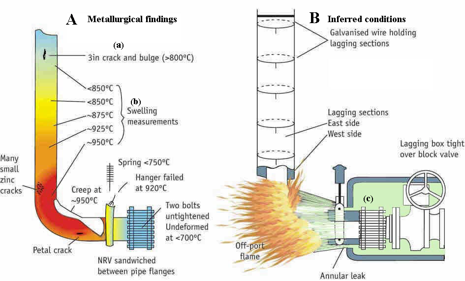
Notes
(a) Zinc embrittlement requires 800-900°C for at least a
fraction of a second whilst the affected surface is free from a
surface oxide layer.
(b) Swelling for 5 minutes and 15 kg/cm2
(normal working pressure) requires the temperatures shown. Longer
periods or higher pressures need lower temperatures for the same
swelling effect. The areas recorded as <850°C had
circumferences within the manufacturing tolerance and may have
been at 150°C throughout.
(c) The preferred exit of a leak from the lagging box may be
presumed to be close to the loose bolts of the non-return valve (NRV).
Initial
leak and ignition
The conjectured escaping
fluid would have been a cyclohexane/water mixture and the
aluminium cladding over the pipe insulation was not electrically
bonded. Para 154 accepted “that gaskets can blow and that
a flashing liquid can produce a charge of static electricity on
conductors such as aluminium” and that this “could
cause ignition”. The contraction and expansion of the
line during the 3-day shut-down could explain the timing of the
gasket blow. Lessons include:
1.
Checking systems should be absolutely dependable to ensure that
flanges are fitted correctly and properly tightened.
2.
Codes of practice for piping material specifications are
appropriate for such services and might usefully recommend a
minimum flanges policy.
3.
There should be restrictions on the use of sandwich
connections (of the type used for the non-return valve
illustrated by Fig 6) in which two gasket joints are held by a
single set of bolts.
4.
Thermal insulation cladding should be electrically bonded on all
equipment, including piping, as is the general practice for
vessels.
5.
Special care on these points is needed with hot two-phase
mixtures because of the extra hazard from static electricity with
oil/water mixtures and flashing liquids14
The
flame from the lagging box
On initial emergence from
the lagging box most of the escape would have been directed
towards the elbow G, roughly as illustrated in Fig 6b. Bluff body
turbulence would have made the off-port flame stable at the
intrados, but this situation would not continue indefinitely. All
parties were “satisfied that ... the lagging box
would have been destroyed and the necessary directional flame
with it” (Para 161). The difference of opinion (Paras
155-157) was over how long the directed flame would last15.
The Court, though not venturing an estimate of its own, clearly
thought 10 minutes excessive.
It became evident during
the hearings that the concept of an off-port flame is not readily
understood, and the fact that aluminium can be and is used for
burner nozzles was met with frank disbelief. It would be most
unfortunate if industry shared this misconception: one lesson
from the investigations is that the location of joints and the
design of lagging boxes should ensure that potential leaks should
not be directed at highly stressed equipment and, where this
cannot be avoided, not from the distance which is the optimum for
flame stabilisation. In principle of course, the most important
precaution is to eliminate the potential leaks but, in
recognition of the impossibility of 100% security in this
respect, it would be useful to leave certain joints unlagged for
inspection.
The
deluge system
As shown in the pre-disaster
photograph 3b, the plant had water deluge protection for vessels
and critical items such as level glasses—although not for
the non-return valve or elbow G. Over one hundred spray nozzles
at the south end of the oxidation unit could be actuated by 68°C
quartz sensor bulbs on a parallel air network, but there was no
evidence that these operated on June 1st.
The nearest sensor bulb
visible on the photograph is over 10 ft distant and this raised
doubts concerning the adequacy of plant protection currently
employed in industry. Experimental work by the Fire Research
Establishment16, assumed that there was an
additional sensor bulb within 5 ft of the elbow, hidden from view
by a water spray. (In Para 160, it is said that there was “convincing
evidence” for a sensor in this position, even though it
could not be found in the wreckage - as were all the others - and
did not appear on installation drawings).
The FRE experiments showed
that there is no certainty that the deluge would have been
activated even by the assumed ‘hidden’ quartz bulb: sensors
that rely on conduction and convection afford much less
protection than commonly supposed. Substantially more
conduction/convection sensors or radiation-activated sensors are
needed. By an unfortunate oversight, the original report on these
experiments, and the calculations refuted in Para 157, are not
listed with the “Reports presented to the Court” (Appendix
VI), giving credence to the claim (Para 160), “No-one
from any sources produced, before the end of our hearings ...
any calculations (to show that the deluge would not have
operated”). Industry needs to be alerted to the far-reaching
implications of this part of the Flixborough investigations.
The
petal and 3 inch cracks
The 8 inch line was lagged
with preformed rock wool sections kept in position by lengths of
14 SWG galvanised wire, wrapped around the sections and spaced 12
inch apart. The twisted ends on vertical sections were laid down
the axis of the pipe as illustrated on Fig 6b and the aluminium
cladding placed over all.
There was a zinc-embrittled
crack on the opened out ‘petal’ of the tulip rupture,
about 12 inch from the expected termination of the lagging on the
horizontal section adjacent to the NRV. The 3 inch crack was
about 5 ft up the vertical section above the elbow and had
been nucleated from (at least) 5 separate points in an almost
precise vertical line (on the east side, by the walkway from
which the lagger would have worked). As these positions were
consistent with zinc embrittlement from expected positions of
galvanised wire (and inconsistent with a random spatter of zinc
droplets), experiments with this wire were undertaken by Cottrell
and Swann. These showed (Appendix II) that such wire could
indeed cause zinc embrittlement.
The Court did not accept
that galvanised wire provided the zinc for these cracks,
apparently because they visualised total disintegration of the
cladding and lagging (with vaporisation of zinc at 907°C). But
experience of small-scale fires shows that preformed sections
will fall after disintegration at only one or two critical points
(at around 600°C). The comment (Para 162) that the Court “cannot
regard (zinc embrittlement from galvanised wire) as a real
possibility” is no guarantee that stainless steel pipe
could not be embrittled in a small fire by galvanised wire.
(Note.
Both hypotheses accepted that the smaller zinc cracks formed
after the rupture of elbow G (Fig 1). However the 20 inch
hypothesis was unable to explain why these appeared only on south
east faces of pipe below the 3 inch crack or how the zinc was
able to penetrate the surface oxide layer formed by several
minutes - at least - of a general fire. As the crack orientations
were consistent with the stress-time sequence of Fig lb (the 8
inch hypothesis), the Court was obliged to attach (Para 187) “no
special significance to the direction of zinc cracks” and
did not proffer an explanation for the stress history of the line).2b
Creep
failure
It was accepted (Para 214)
that fracture through creep “can be produced in a matter
of minutes by a small fierce fire” but not accepted (Para
162) that the envisaged flame from the lagging box could have
raised the pipe temperature to over 900°C. Experiments by Gugan
achieved red heat from flame impingement on a pipe containing
flowing water but were criticised on the grounds that the flow
rates used were too low and that, in practice, liquid would have
swept away the vapour blanket needed for such temperatures to be
attained.
Unfortunately the actual
flow conditions were not known. As the plant was recirculating
prior to start-up, low circulation could have been expected and,
in confirmation of this, the discharge valve on the pump was
found throttled (Fig 2). But the flow was level-controlled and
the circulation could have been varied without adverse effects.
DSM suggested that the flow could have been one-third of normal
and this was used by Gugan as basis for his experiments. However,
once the 3 inch crack had opened (this required no more than 800°C
at the outer surface), the flow through the elbow would have been
reduced by at least half that figure (to around 25 lb-s-1).
The flow would have been
further reduced as a result of vaporisation of the cyclohexane/water
mixture and, above 500°C, by decomposition of the cyclohexane
into benzene, hydrogen and carbon. The consequence of extra
pressure drop downstream from elbow G (and the throttle valve)
would have been less flow and even more vaporisation. Such
factors, well known to boiler engineers, show that large flows
do not necessarily provide pipes with protection from high
temperatures in a fire.
Stronger pipe would delay
but not avoid creep failure. The more fruitful approach is to
eliminate the factors that might cause such a fire. The creep
failure investigations have emphasised the vulnerability of
plants to small fierce fires—the main overall lesson from
the 8 inch line hypothesis.
8 Lessons from a Public
Inquiry
Long before the SMRE
experiments were concluded, or the Cottrell/Swann investigations
even begun, Nypro’s technical advisors were rebuked publicly
by the Chairman of the Court because they were not prepared to
express a view on the cause of the disaster. The fact that we
waited until the evidence was available does not prove us right -
or the Court wrong - but it does illustrate that a public inquiry
is not necessarily the best way to conduct a technical
investigation. The procedures encourage rigid and premature
postures to be adopted and discourage investigation in depth.
Moreover, having come to a
conclusion, a Court will tend to concentrate on arguments germane
to its own conclusions and so undervalue other potential lessons.
Paras 116-117 and 166-171 typify this approach. A cine-film taken
from location 31 (Fig 4), within a minute of the explosion, shows
a vertical phenomenon “said to be a near vertical
turbulent jet of flame coming from the rupture in the 8 inch line”
The Court agreed that if a vertical flame could come from the
ruptured elbow, this “would strongly support the 8 inch
hypothesis “. To test this conjecture, a ¾ inch plastic
elbow was made which copied the geometry of the rupture. On
discharge, this produced a substantial upwards component thus
emphatically reinforcing the 8 inch hypothesis.
The report does not
mention this experiment, specifically designed to give a
realistic simulation of (he direction of emission from the
ruptured elbow, but refers, instead, and at length, to
experiments on a different topic, with a ¼ inch elbow which “did
not ... attempt to reproduce the “tulip” effect
in the original split “. The Court concluded this
section with the stricture (Para 172), “We have dealt
with this particular point in some detail for it appears to us to
be a good example of the way in which the enthusiasm for the 8
inch hypothesis felt by its proponents has led them to overlook
obvious dejects which in other circumstances they would not have
failed to realise.”
This same point is
mentioned for it is a good example of the way in which the Court’s
commitment for the 20 inch hypothesis led them to present their
conclusions in a way that does not help the reader to assess
contrary evidence. The Court could still be right that a single
unsatisfactory modification caused the disaster but this is no
reason for complacency. There are many other lessons. It is to be
hoped that the respect normally accorded to the findings of a
Court of Inquiry will not inhibit chemical engineers in looking
beyond the report in their endeavours to improve the already good
safety record of the chemical industry.
Acknowledgements
Thanks are due to
colleagues of L. H. Manderstam and Partners (UK) Ltd, and other
coworkers on the investigations and to Nypro (UK) Ltd, for many
helpful suggestions in the preparation of this paper. The views
expressed are entirely my own personal responsibility.
References
1
Cottrell. A. H. and Swann, P. R.. Chem Eng. (London). April
1976. p. 266
2
BalI, J. C. Chem. Eng. (London). April 1976. p. 275
a ibid Section 4.1
b ibid. sections 4 & 5
3
Gugan, K., Chem. Eng. (London), May 1976, p. 341
a ibid. section 4.2
b ibid. Fig 2
4
Waterhouse, D. and Games, G. A. C., Construction of and
tests on a reconstructed bridging pipe assembly, SMRE report
to Public inquiry
5
Newland, D. E., Report on an investigation of possible causes
of failure of the 20-inch by-pass assembly at Flixborough, Report
to Public Inquiry
6
Appendix I and Para 124 of Court’s Report and Ref. 5
7
King, R., Process Eng., September 1975, p. 69
8
Evans, G. O. H. M. Factory Inspectorate, Private communication.
9
For example, Professor Sir Frederick Warner’s Proof of
Evidence, page 41 and the preliminary Police Report, page 39.
10
The eye-witness at location 15 of Fig 4 could not see the
plant and the spectacular vapour escapes (and flames) because of
a control room. He reported* (Day 3, pp 81-91) an object
something like a “round disc spiralling in the air
... with a 6 ft wide cone of flames beneath it ... about 3 ft
wide ... about 100-120 ft up immediately after the explosion (i.e.
(initial noise) ... by the time 1 just turned my head around.”
He estimated its flight as up from Section 27 and down to the
Flaking Plant. As he was 600 ft away, this could well describe
the trajectory of the furthest flung fan rotor (see Fig 4) which
was “waggling about a little (as if) on a central axis”
(as might be expected from the object with a thin shaft and small
counter-weight shown on Fig 5).
11
Elliott, D., Zinc embrittlement of stainless steel - A
postscript to Flixborough, (Unpublished). At the Nottingham
symposium, Dr D Elliot reported that British Steel had conducted
tests on this phenomenon and were confident that a satisfactory
technical solution had been found.
12
All the more than thirty eye-witnesses with a clear view of the
area reported flames prior to the major explosion (Fig 3).
Moreover, whereas the earlier viewers reported flames moving
outwards, others reported the opposite movement.
13
Foley, J. H. and Nicholson, C. E., Metallurgical examination
of damaged pipes from section 25A, SMRE report to Public
Inquiry.
14
Klinkenberg and van der Maine, Electrostatics in the Petroleum
Industry, Elsevier and Guide to Fire Protection in the
Chemical Industry. CIA.
15
The metallurgical evidence indicated that 4 minutes would cause
creep failure at 950°C and working pressure so, allowing for
heating-up, a slightly longer period would have been necessary in
practice. No one was in a position to see the flame but the
witness at location 25 (Fig 4) saw a “wisp of steam” 3-5
minutes before the main explosion (Para 112) rising from behind
Reactor 3 (i.e. the position of the 8 inch line). He did not
recall seeing this emission only a ‘few’ minutes
earlier, suggesting perhaps that the time from gasket failure to
creep rupture was less than, say, 10 minutes.
16
Nash, P. and Theobald, C. R., The use of automatic sprinklers
as fire sensors in chemical plant, Paper to Nottingham IChemE
symposium, December 1975.
*
ADDITIONAL NOTE (2005) see Flixborough FAQs
for further details of this eyewitness evidence.